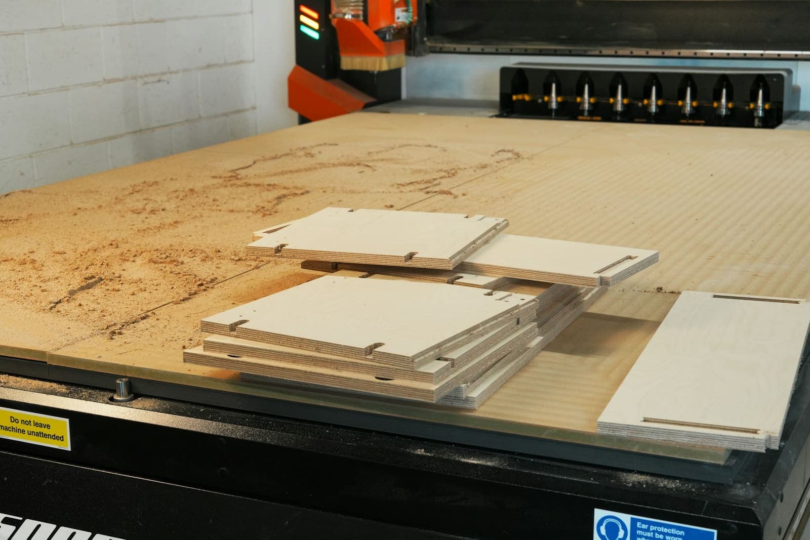
Many joinery workshops still draw in 2D and program the CNC separately. Modelling in 3D links the design, the cut list and the machine. Here are nine benefits, and how to start.
IN SHORT
- 3D CAD links the design, cut list, hardware and CNC files in one model, so they always agree.
- The biggest gains are fewer cutting errors, faster design changes and quicker client approvals.
- You can get the benefits without buying software, by outsourcing 3D modelling to a team that works in SWOOD or iMOS.
In a traditional joinery workflow, someone draws the job in 2D, someone else works out the cut list, and the CNC is programmed separately. Each step is a chance for a number to be copied wrong. 3D CAD changes that: the model becomes the single source for drawings, parts lists and machine files.
1. Accurate cut lists, automatically
Every panel in the model has its real size, material and edge banding, so the cut list comes straight from the model instead of being worked out by hand.
2. CNC-ready output
Tools such as SWOOD and iMOS generate drilling, grooving and nesting data from the model. Panels go to the CNC with labels, which saves programming time and avoids transcription errors.
3. Clashes found on screen, not on site
A drawer that hits a hinge, a door that cannot open past a wall, a handle that clashes with an appliance. In 3D these show up before anything is cut.
4. Faster design changes
Change a cabinet width or height and the parts, drilling and drawings update with it. In 2D, every view and the cut list need editing by hand.
5. Quicker client approvals
Clients and designers understand a 3D view or render far more easily than a section drawing. Fewer misunderstandings mean fewer revision rounds.
6. Consistent construction standards
Standard carcasses, joints and 32mm system drilling can be built once into a library and reused, so every job follows the workshop's way of building.
7. Hardware placed correctly
Hinge, runner and connector libraries place hardware with the right drilling patterns, and the hardware schedule is generated with the model.
8. Better quoting
Board quantities, edging and hardware are known before the job is priced, so quotes are based on the real design rather than estimates.
9. Drawings and machine files that always agree
Because shop drawings and CNC files come from the same model, the drawing the client approved is the part the machine cuts.
THE REAL WIN · ONE MODEL FEEDS THE DRAWINGS, THE CUT LIST AND THE CNC. NOTHING IS COPIED BY HAND.
2D vs 3D for joinery at a glance
| 2D WORKFLOW | 3D WORKFLOW | |
|---|---|---|
| Cut list | Worked out by hand | Generated from the model |
| CNC programming | Separate step | Generated from the model |
| Design changes | Edit every view and list | Change once, everything updates |
| Clash checks | Mental, or found on site | Visible on screen |
| Client approval | Plans, elevations, sections | 3D views and renders as well |
How to get started
Moving to 3D usually means new software, training and building libraries, which is a real investment for a busy workshop. A practical alternative is to outsource the 3D modelling, shop drawings and CNC outputs to a team that already works in SWOOD and iMOS, and keep your workshop focused on building.
Questions people ask
What software is used for 3D joinery and cabinet design?
SWOOD, which runs inside SolidWorks, and iMOS are widely used for 3D millwork and cabinetry, producing cut lists, drawings and CNC outputs. Other dedicated cabinet design packages are also common.
Is 3D CAD worth it for a small joinery workshop?
Often yes, mainly through fewer cutting errors and faster changes. If buying and learning software is not practical, outsourcing the 3D modelling gives the same outputs without the investment.
Can 3D CAD send files directly to a CNC router?
Yes. Tools such as SWOOD and iMOS generate drilling, grooving and nesting data for the CNC, usually through a post-processor set up for the specific machine.
Do I still need 2D shop drawings with 3D CAD?
Usually yes, for approvals and installation. The difference is that they are generated from the 3D model, so they always match the parts being cut.